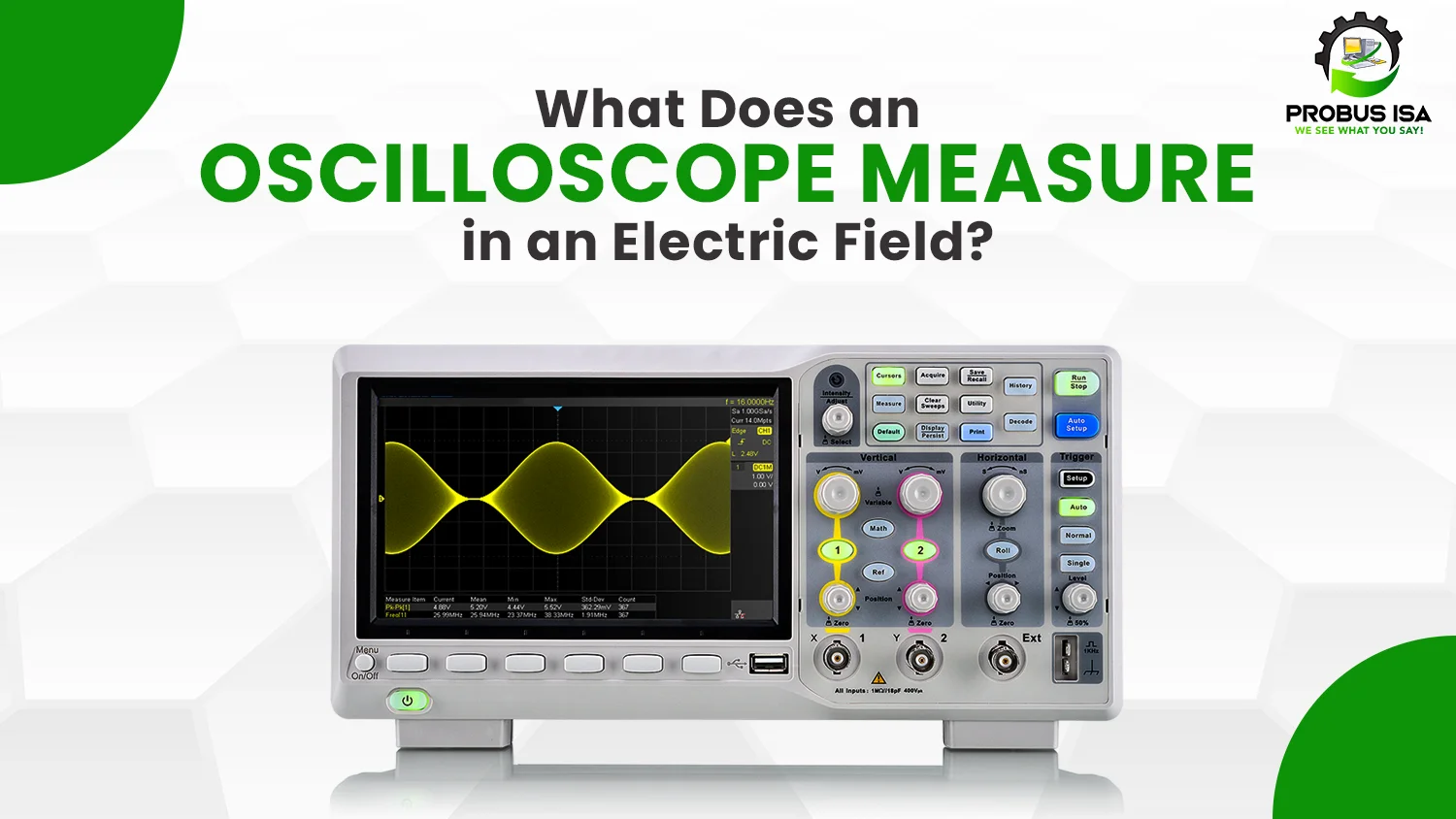
In the late 1800s, Oscilloscope was invented to measure high-speed voltage changes. It is an electronic measuring system that captures the waves in the electrical field and measures voltages. However, the most common concept people are curious about is what is the oscilloscope measure.
Over the years, oscilloscopes have evolved in function and working capacity. Their enhanced function made them easily applicable experimentally to laboratory measurements. They have made the complex everyday work of scientists and electrical engineers easy. It is used more in students’ and professors’ major electronics and electrical engineering research.
But what is the science behind this amazingly working oscilloscope? How does it capture the unseen waves and show the frequencies of these waves and signals? Let’s delve into the parts of the oscilloscopes and how to use them to their full potential.
The Evolution of Oscilloscopes
Oscilloscopes have evolved very interestingly. Transformation to today’s oscilloscope was a series of inventions. The oscilloscope has come this far from a basic tool to an advanced research instrument. The different types of oscilloscopes over the years are:
Oscillograph
The first oscilloscopes were called oscillographs. These oscillographs relied on mechanical parts to record fluctuations in electrical signals. Although they were slower and had lower resolutions, they remained important developments for testing and analyzing initial electric signals.
Cathode ray tube
A cathode ray tube contains a display of a phosphorescent screen on which they present the signal as a waveform on a phosphorescent screen. This way, electrical behavior was now observable in real-time without mechanical recording and with considerably faster signals to be measured.
Analog Oscilloscopes
By the mid-20th century, analog circuits were the basis for the presentation of waveforms. However, they could neither store nor manipulate data in the digital format. As such, they were not as applicable in more complex analyses.
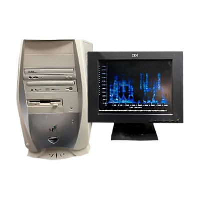
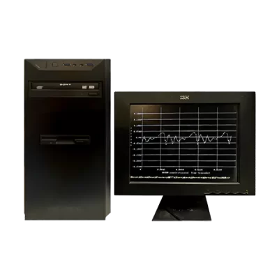
Digital Oscilloscopes
Digital oscilloscopes were introduced in the late 20th century. They employed microprocessors and digital storage, transforming analog signals into digital data. They made analyzing, storing, and sharing waveforms easier and incorporated facilities such as automatic measurements, signal processing, and multi-channel analysis.
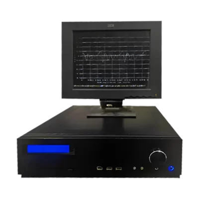
Contemporary Oscilloscopes
The most recent oscilloscopes include multiple-channel inputs, sophisticated triggering systems, and USB and Ethernet connectivity. Applications have evolved to cut across every type, including telecommunication, automotive engineering, and medicine. Some even contain software that analyses data generated and prints out reports.
How does an oscilloscope work
Simply put, an oscilloscope determines volt/div over time. The data is shown graphically, with time on the X-axis and voltage on the Y-axis. A modern oscilloscope can also measure parameters such as frequency, amplitude, and current depending on the probes used.
What Does an Oscilloscope Measure?
An oscilloscope is a multi-purpose device that lets you measure and analyze many aspects of the electrical signal. These measurements are crucial for understanding signal behavior, finding faults in an electrical circuit, or ascertaining that systems behave electrically as designed. Here are the primary measurements of an oscilloscope:
- Voltage
The most basic measurement an oscilloscope provides is voltage. It will display amplitude in a vertical direction within the oscilloscope. An oscilloscope reads different forms of voltage, including instantaneous voltage (lowest point), peak voltage (the highest possible point or the zero line), and peak-to-peak voltage (total sum of the voltage).
- Time and Frequency
The X-axis of an oscilloscope is time, so you can measure the period of a single waveform cycle and calculate the signal’s frequency. These parameters are important for understanding how often the signal repeats and its timing characteristics:
- Period (T): The time it takes for one complete cycle of the waveform.
- Frequency (f): The number of cycles per second, calculated as f=1/T.
Time and frequency measurements become very important in applications that include communications, where appropriate timing and frequency control play a crucial role.
- Amplitude
Amplitude measures how strong the signal is. It is usually measured in peak-to-peak value. It measures the voltage difference in the waveform between the two extreme points. A strong amplitude indicates a strong signal, whereas variations in amplitudes may indicate an issue such as signal degeneration or interference.
Maintaining the signal’s amplitude is important in amplifiers, audio systems, and power supply design; hence, amplitude measurements are very important.
- Waveform Shape
The waveform shape describes the type of signal and integrity. The common shapes of waveforms are:
- Sine Wave: Smooth and continuous, related to AC power and audio signals.
- Square Wave: Alternates between two levels and is used in digital circuits.
- Sawtooth Wave: A linear rise but steeper fall, with widespread use in signal generators.
Irregular Waveforms are responsible for noise or distortions within the circuit. Shape analysis of waves allows engineers to analyze distortions, noises, or unexpected system functions.
- Current
You can measure current with an oscilloscope. It indirectly uses special probes called current probes or can mathematically transform a voltage applied across a known resistance. Calculations for current are useful in evaluating the amount of energy circulating through a circuit and checking that components are within the limits of their operation.
- Phase Difference
The comparison of two signals with a phase difference determines their timing concerning one another. This applies most importantly to applications like the following:
- Signal Synchronization: Ensuring several signals are aligned correctly.
- Power Systems: Analyzing the phase relationship between voltage and current to calculate the power factor and efficiency.
The oscilloscope simultaneously displays both signals on its screen, allowing precise measurement of the time offset or phase shift between them.
Get Accurate Oscilloscope Measurements
There are some measures you must focus on to get accurate oscilloscope measures or readings.
Use Proper Probes
Employ probes dedicated to your signal’s bandwidth. Calibrate them to your oscilloscope settings. Make sure a good, solid ground connection exists close to the measurement point to help reduce noise and interference.
Adjust Settings
Set the vertical (voltage) scale to clearly show the signal’s amplitude and adjust the horizontal (time) scale to show a clear waveform with enough cycles. Proper trigger settings stabilize the waveform and avoid jitter or instability in the display.
Minimize Noise
In addition, to reduce errors due to measurements, work in a low-noise environment and use shielded cables to prevent electromagnetic interference. Match the oscilloscope’s input impedance to the circuit’s impedance to avoid signal reflections, which may distort measurements.
Calibrate Periodically
Regular calibration of the oscilloscope and probes ensures that the oscilloscope maintains its accuracy over time. Periodic calibration checks will help ensure that the oscilloscope remains within the specified performance limits.
To Sum up
The oscilloscope is the best mechanical tool for measuring and analyzing electrical signals. Understanding voltage, time, frequency, amplitude, waveform shapes, current, and phase differences is important. The oscilloscope measure offers valuable insights into telecommunications, medicine, automotive engineering, and more industries.
Whether you’re a student learning the basics, an engineer troubleshooting a circuit, or a scientist conducting cutting-edge research, the oscilloscope is a gateway to understanding the electrical world. Its evolving capabilities continue to empower innovation, ensuring its relevance for years.